- Home
- Compare Systems
- Cheap Systems
- Free Quotes
- DIY Systems
- Hardwired Systems
- Wireless Systems
- Smoke Detectors
- Medical Alarms
- Alarm Monitoring
- Cameras & Video
- Ademco
- ADT Security
- Brinks Security
- Broadview
- DSC Security
- FBI Alarms
- GE Security
- Honeywell
- Link Interactive
- Monitronics
- Moose
- Napco
- Protection 1
- Radionics
- Simplisafe
- Alarm Manuals
- Alarm System Parts
- Alarm Tools
- Troubleshooting
- FAQ
- Glossary
- Sitemap
- About Me
- Contact Me
Smoke Detector Circuit Basics
Fire Protection for Home Security Systems
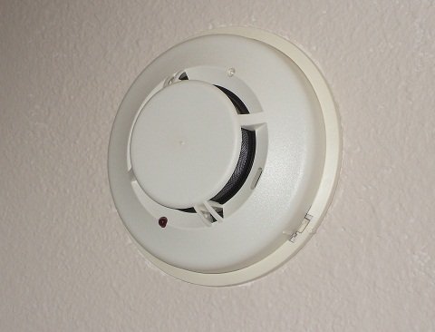
Smoke Detector Loops on Alarm Panels
A smoke detector circuit is built into many home security systems. Also
known as a "smoke loop", this circuit uses low-voltage smoke detectors,
powered by the alarm system panel.
Unlike standard 110-volt home smoke detectors, which only make noise at the house, the low-voltage units allow fire alarms to be reported to a central monitoring station. Help can be on the way almost as soon as smoke is detected, often before the occupants are aware of it.
Some panels that support fire alarm connections only provide a single set of terminals. Often though, it's necessary to pull more than one smoke wire to reach all the detectors in the system. See how to handle this situation here: Smoke Detector Wiring - Connecting Multiple Runs.
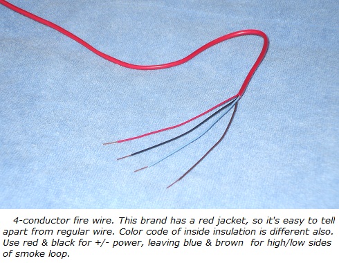
In many areas, electrical and fire codes require the use of special fire-rated cable for connecting residential smoke detectors. This “fire wire” has jacketing material that is rated to withstand high temperatures longer than standard wire, so it should be the last to burn in case of a fire. This gives the system a better chance to alert occupants and transmit a report to the central monitoring station.
Fire wire is normally 22-gauge for residential use, and can contain either 2 or 4 conductors.
The low-voltage smoke detector wiring
is completely separate from the
standard 110-volt smoke alarms, and is wired in a specific way.
Trouble Conditions
The security panel is designed to sense any problems on the smoke detector circuit. These trouble conditions can include:
- Open Circuit – A wire is cut or disconnected at some point in the loop.
- Short Circuit – A portion of the wiring is effectively bypassed. Usually due to loose or damaged wires touching each other.
- Ground Fault – A wire is in contact with a grounded conductor. This often means wiring has been damaged, and is touching ductwork, framing, or other metal.
The ability to sense problems like this is called
“supervision”. Supervised loops often include an “end-of-line resistor”,
EOL resistor, or just EOLR. This resistor is located at the end of the
wiring run (oddly enough), and is used to detect a shorted condition.
The System Sensor smoke detector circuits, shown below, are typical of most other manufacturers.
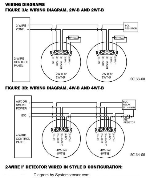
The diagram shows the two basic types of smoke detectors, 2-wire and 4-wire. Most home alarm panels are designed to handle one type or the other, but some can handle both. Here’s how they work:
Two-wire Smoke Detector Circuit
Power to operate the smoke detector is supplied on the same 2 wires
as the detection circuit. A 2-conductor cable goes from the main panel,
connects to each smoke in sequence, and terminates with an EOLR at the
last detector.
In normal operation, the alarm panel “sees” the EOLR, so it
“knows” that all the connections are good. If the detector senses smoke,
it creates a short across the pair of wires, and the panel goes into
alarm.
If a wire is cut, or pulls loose from a screw terminal, the panel no longer sees the EOLR, and it signals an open trouble condition.
In case the wires are shorted, the panel will go into alarm, since this is the same condition caused by the detector when it senses smoke.
Learn more about Connecting 2 Wire Smoke Detectors.
Four-wire Smoke Detector Circuit
Power for the device is supplied on one pair of wires, or loop, while the detection circuit is connected to a second pair. The cable runs from the main panel, and connects to each smoke detector in the system. At the last unit, the detection circuit terminates with an EOLR, just like the 2-wire smoke.
In operation, the detection loop acts the same as with a 2-wire
smoke detector circuit. The panel senses the EOLR as long as the loop is
closed, and signals a trouble condition if it opens. If smoke is
detected, the pair of wires is shorted, causing an alarm.
Unlike the 2-wire detector, the power loop must also be supervised. A power supervision relay is connected with its coil energized by the power loop,
and its contacts in series with the detection loop.
As long as the relay gets power, the detection loop stays good.
If a power wire is cut or comes loose, the relay loses power, and the drops out. This opens
the detection loop, and the panel signals an open-circuit trouble condition.
For more information, see Connecting 4 Wire Smoke Detectors.
Source for a power supervision relay.
Making the Connections
Most smoke detector manufacturers include a wiring diagram with every unit, so you can quickly see how to make connections. It’s a good idea to leave a copy in the main alarm panel, for future reference. (This goes for any device installed in the system, for that matter). Besides the wiring diagram, the installation sheet will also contain instructions on how to test and maintain the unit.
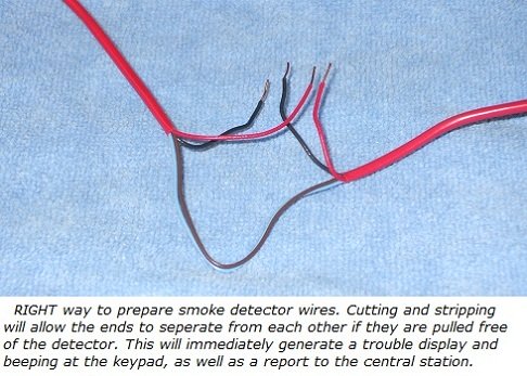
When making connections at the last detector in the run, you’ll obviously be stripping the wire ends to attach to the screw terminals.
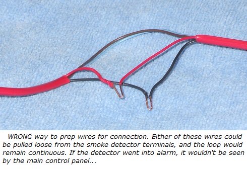
When making connections to a looped smoke detector location, you’ll have a loop of wire to deal with. In this case, always cut the wire. While it may be easier to simply strip off some insulation and fold the wire over, don’t do it. Why?
If, someday down the road, the smoke detector wire is pulled on, the wire may come loose from the screw terminal. If you’ve simply folded over the wire, the smoke detector circuit will still appear to be intact from the alarm panel’s point of view. No trouble condition will be generated, even though the wire is now no longer connected to the smoke detector!
This leaves you unprotected, but still thinking the system is
working properly. The panel is actually unable to trigger an alarm from
that detector.
Had the wire been cut at the time of connection, the ends would have separated when pulled loose, causing an open trouble condition.
For tips on finding problems with smoke detector wiring, check out these articles:
For wiring at the main panel, see
Smoke Alarm Circuit Troubleshooting.
For wiring at the smoke detectors themselves, see
Troubleshooting Smoke Alarm Wiring.
For details on connecting smoke detectors and other devices to a typical alarm panel, see Ademco Vista 20P Wiring Diagram.
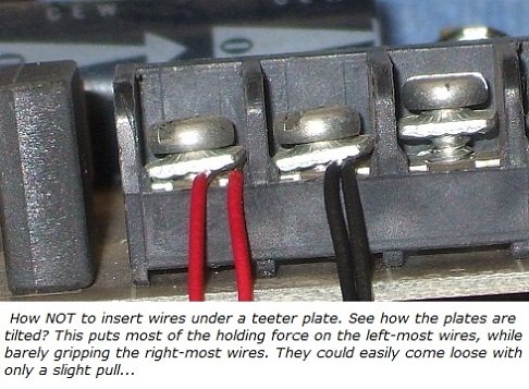
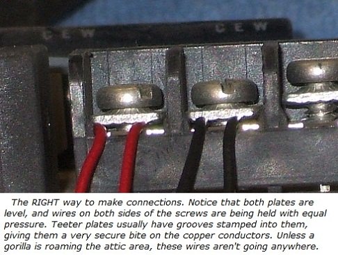
Types of Smoke Detector Circuit Terminals
Screw terminals vary from unit to unit. Older style smoke detectors
use standard screws with teeter plates. Teeter plates hold wire more
securely than a screw head alone, and also make connecting more than one
wire easier.
Many newer designs of smoke detector use terminal strips or detachable terminal blocks. These speed up wiring a bit, but you’ll need a fine-tipped screwdriver to tighten them.
With any kind of wiring connector, don’t over-tighten the screws.
They are small enough that they can be easily stripped, making the wire
forever prone to coming loose. Just snug them up good, without using
your “Kung Fu” grip.
For more information on residential smoke detectors for home alarm systems, see this page on Hardwired Smoke Detectors.
For tips on where smoke detectors should be located in a house, see Smoke Alarm Placement for Home Security Systems.
For information on cleaning smoke alarms, see System Sensor Smoke Detectors, Cleaning and Testing.
Confused by home alarm pricing? Get the inside scoop on home security prices from an experienced alarm professional.
If you haven't done so already, get a few Free Home Security Systems Quotes from companies in your area.
This will give you a good idea of what it would cost to have a system installed, as well as how much you could save by doing it yourself.
Return to Home-Security-Systems-Answers from Smoke Detector Circuit Basics
Return to Hardwired Home Security Systems from Smoke Detector Circuit Basics
Return to Home Smoke Detectors from Smoke Detector Ckt Basics
Note: Feel free to print any of the articles on this site for personal, non-commercial use. Just look for this button:
If you found this website especially helpful, you might want to consider making a small donation. Since 2011, AzAlarmGuy has been providing free help and advice on home security systems to all of those in need.
Your gift, in any amount, will help me keep this website a free resource for anyone needing help with alarm system issues or questions.
Disclosure
I receive affiliate commissions from some of the companies and products I discuss. These commissions don't change the price that you pay.
Rest assured that this compensation does not influence my recommendations. I only endorse products and services that I truly believe to be an honest value for you, as a visitor to my site.
For more details, see my full disclaimer.


